|

|
|

Using Coax to Distribute Advanced IPTV Services in the Home
By: Bud Bates
|
This month we talked with Andy Melder from Intellon Corporation about how power lines in a home can be used to distribute data and multimedia content in the home. Intellon has worked with the HomePlug® Powerline Alliance to assist in the development of a high-speed data and multimedia distribution technology known as Home Plug AV. It allows consumers to utilize their in-home power grid as a broadband backbone through which to distribute rich content or data throughout their homes. Broadband over Power Line (BPL) BPL characterizes the process of sending data or content over the same wires used to transfer power to the home (electrical lines). Sending data over power lines is not new. Several power line communication systems have been available since the 1970s. The earliest power line communication systems were used to transfer control information for home automation. These early power line communication systems sent a limited amount of data (control signals) at relatively low frequencies when compared to today's much more sophisticated power line communication systems. BPL systems to the home typically start from a feeder cable (drop) to the home that is run from a nearby step down transformer. A step down transformer is a coupling device that changes a higher voltage to a lower voltage (steps down). Step down transformers often produce electrical signals that have two or more phases. Powerline Communications (PLC) Systems PLC systems define the use of the "in-the-home" power grid for broadband communications for various consumer applications such as content delivery and provisioning, command and control, data networking and VoIP. Again, PLC as a technology is not new. What has changed in the past decade is the level of sophistication and advances made in signal processing algorithms, forward error correction (FEC) techniques, advances in silicon process geometries and general trends in Moore's Law. |
An important change in PLC technology took place in 2001 with the introduction of a true global standard known as HomePlug, introduced by a group of semiconductor companies led by Intellon Corporation. With the acceptance of a PLC standard, the industry was assured that other silicon providers building devices according to the HomePlug specification, would interoperate with other devices built in similar fashion. Finally, the advances in digital communications technologies listed above have driven performance from kilobits/second in the mid 80s to the current state-of-the-art performance metrics in devices such as Intellon's HomePlug AV compliant 200 Mbps PLC transceiver. In addition, major advances have been made in noise immunity and Quality of Service (QoS) mechanisms-- perhaps the strongest arguments in the past for not using PLC technologies as a broadband backbone in the home. This is especially important given the levels of performance that service providers have delivered such as DOCSIS signaling, various flavors of xDSL technologies and the next generation of Passive Optical Networks (PON). In-home PLC technologies, now led by the HomePlug Powerline Alliance, provides a robust broadband backbone that delivers a payload of various forms of data and content throughout an entire home, with high degrees of noise immunity, a strong QoS mechanism built in, resistance to interference and with an ease-of-use model and price point that the consumer finds very attractive. Why is an Intelligent Power line IPTV Premises Distribution Network (PDN) Important? Power line premises distribution for IPTV is important because televisions, Set-Top Boxes, Digital Media Adapters (DMAs) and other media devices are already connected to power outlets already installed in a home or small businesses. These lines can be used to transmit rich multimedia content where it is desired. Intelligent powerline distribution systems are able to adapt to the varying characteristics of the in-home power grid and should be able to transfer media between any device enabled to "hear" the content |

|
being distributed on the powerline. Powerline distribution systems convert
the different types of media (Internet data, Voice-over-IP packets, or IP
video streams) into information that is modulated onto high frequency
carriers imposed on the powerline. Power Line Command & Control Power Line Command & Control (PLCC) is the use of the in-home power grid for sending home automation type signals. The power line communication systems developed in the 1970s used relatively low frequencies such as 450 kHz to transfer data on power lines. The amount of data that could be transferred was limited and the applications typically consisted of controlling devices such as light switches and outlets. Some of the early home automation systems include: X-10, CeBus and LONworks. Power line communication signals travel from their entry onto the home power line system (typically from a powerline-enabled broadband modem such as WiMAX, DSL or cable, or a fiber optic Network Interface Device in the home), through a variety of conductive powerline pathways until it reaches a destination device. The percentage of outlets or electrical devices within a home that can receive and process power line data signals is referred to as a statistically derived "home coverage" figure. The power line communications coverage within a home is expressed as a rate of speed over a certain percentage of outlets. Therefore, as an example, 25 Mbps at 80% coverage should be interpreted as 80% of the power outlets in a house will provide at least 25 Mbps in bandwidth. This is different than an average performance figure. The home coverage figure is important to a service provider, as it defines a relative throughput performance index within an average home for some percentage of total outlets. A number of factors influence overall performance, including the distance the signals have to travel (size of home), the size of the wire, and the number of unterminated outlets. Older (legacy) power line communication systems had |
challenges with the phase of the power and especially noise impairments
like brush motors, halogen lamps and dimmer switches. Today, with the
benefit of modern signal processing techniques and algorithms, most of
these impairments no longer are an impediment to performance. Whereas in
the past, a powerline communications device only provided connectivity to
70-80% of the outlets reliably, today with HomePlug, connectivity to any
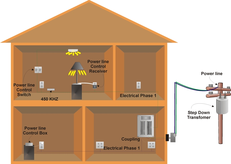
outlet in a home is a virtual certainty. Looking at the early implementations of powerline communications systems, much of the coverage challenge was due to the difficulty of powerline communication signals to propagate on electrical powerlines that are on different phases. The amount of signal energy that transfers across power lines that are connected to different phases of a home's power grid is called cross phase coupling. To help the power line communication signal to cross over different phases of an electrical system, cross phase couplers could be installed. While some of these cross phase couplers could be installed by the homeowner at outlets that had both phases (e.g. a dryer outlet), cross phase couplers improved the home coverage ratio, but the improvements were not always enough to solve the overall challenges of connectivity and as a result, operation of these home automation systems were not always reliable. Figure 1 shows how existing power line distribution systems in a home (such as X-10) can distribute data signals in a home. This diagram shows that medium voltage electricity (6,000 to 16,000 Volts) is supplied to a step down transformer near the home. This transformer produces two or three phases of power ranging from 110 V to 240 V. These electrical signals pass through an electrical distribution panel (circuit breaker panel) in the home to supply outlets and lights. This diagram shows an X-10 power line communication system where an X-10 switch in the wall controls an X-10 outlet receiver by sending control signals over the power line on the same circuit (same phase) to allow a user to control a lamp. This example also shows an X-10 power line control box plugged into another outlet on a different cir |
|
|
|
66 March 2006 Definitions FREE at www.IPTVDictionary.com

|
|
|
| Figure 1, Power Line Communication Control System | |
|
cuit (different phase) and the control signal must cross over from one
phase to the other phase (cross over in the electrical panel) so it can
reach the X-10 outlet receiver. Home Data Networking Home data networking is the process of transferring data in a customer's home or personal area. Home data networking can connect computers and other data communication devices (such as printers) to each other so they can send and receive data between each other. Although power line communication systems could technically transfer data in the 1970s and 1980s, improvements in the power line data transfer rates necessary for home data networking did not occur until the early 2000s. Part of the motivation to make advances in power line communication was the increased need for home networking. HomePlug 1.0 A significant improvement for power line communication came with the release of the HomePlug 1.0 specification in 2001. The HomePlug system transfers data through existing power lines at 14 Mbps using higher frequencies (from 4 MHz to 21 MHz) which allows a signifi |
cant improvement in cross phase coupling. These higher frequencies allow
the signal to couple phases in the electrical distribution panel. As a
result, the coverage of HomePlug power line communication systems
approached 99% without the need for cross phase couplers or professional
installers. As the signals travel down the power lines, a portion of the signal is lost through the wires (absorbed or radiated). Signal frequency, the type of wire, how the wire is installed and the length of the wire are key factors in determining the amount of energy that is lost. Generally, as the length of a power line increases and the number of outlets increases, the amount of attenuation also increases. Signal loss at high frequencies through power lines can reach 50 dB and the dynamic range of HomePlug devices can be between 70 dB to 80 dB. Because it is possible for HomePlug signals to travel on power lines shared between several homes, the signals are encrypted to keep the information private. The HomePlug 1.0 system encrypts (scrambles) information using 56-bit DES security coding. Only devices that share the same HomePlug encryption codes can share the information transferred between the devices. One of the significant challenges for power line communication systems is the "sources and effects" of interference signals that can distort power line communication signals. Interference signals include motor noise, signal reflections, radio interference, changes in electrical circuit characteristics, variability in the amount of coupling across dif
|
|
ferent phases of electrical circuits and stray transmission. The HomePlug
system was designed to overcome these types of interference and in some
cases, the HomePlug system can take advantage of them. Motor noise is the unwanted emissions of electrical signals produced by the rapidly changing characteristics of a motor assembly. In most homes, motors are in a variety of appliances and they may be used at different locations at any time. The HomePlug system can adapt in real time to the distortions caused by motors and appliances. Signal reflection is the changing of direction that a signal travels as it passes from one transmission medium to another (transmission channel or device). When the characteristics of the media are different (impedance), a reflected signal is generated. Some of the energy of the forward signal (incident signal) is redirected (reflected) back towards the signal source. When high-frequency HomePlug signals reach the ends of power lines, some of their signal energy is reflected back towards the transmitter. These reflected signals combine with the forward (incident) signals producing distortion. The HomePlug system includes sophisticated analysis of the signal and it is possible to use the signal reflections as an advantage rather than a challenge. Some of the frequencies used by HomePlug systems are the same radio frequencies used by citizen band (CB) radios or AM broadcast radio stations. The HomePlug system divides the frequency band into many independently controlled sub-channels (using a modulation scheme known as Orthogonal Frequency Division Multiplexing - OFDM) so that when interference is detected (such as from a hair |
|
||
|
|||
|
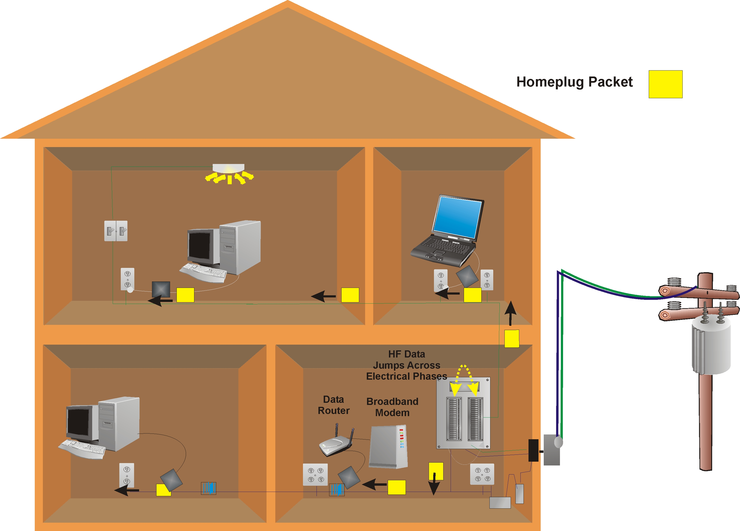
circuit breakers and travels down the electrical lines to reach the HomePlug 1.0 adapter connected to a printer. This diagram also shows that the computer can send data signals down the power line to a HomePlug router connected to a broadband modem allowing the computer to connect to the Internet. Home Media Networking Home media networking is the transferring of rich multimedia signals throughout the home where they may have different transmission and quality of service (QoS) requirements. HomePlug AV The HomePlug Audio Visual (HomePlug AV) specification was ratified in 2005 by the HomePlug Board of Directors, to provide home media networking. HomePlug AV was designed to give priority to media that requires time sensitive delivery (such as IPTV) while allowing reliable data communication (such as web browsing) to simultaneously occur. HomePlug AV uses a mix of random access (unscheduled) and reserved access (scheduled) data transfer. The carrier sense multiple access with collision avoidance (CSMA/CA) protocol, provides for efficient transfer of bursty data while the scheduled TDMA system ensures real time media (such as digital video and audio) will be delivered without delays and will take priority on the wire over CSMA/CA traffic. The HomePlug AV system is designed to be a 200 Mbps-class PHY device. Actual application layer performance will be less than that, as MAC efficiency needs to be contemplated in overall performance measurements. HomePlug AV uses a significantly higher spectrum (from 2 MHz to 28 MHz) which allows for good cross phase coupling because these higher frequencies can jump across circuit breakers to increase the signal availability in the home. Like HomePlug 1.0, the coverage of HomePlug AV power line communication systems approaches 99% without the need for cross phase couplers or professional installers The HomePlug AV system uses a more secure 128-bit AES encryption process to keep information private. The HomePlug AV system has better control of transmission delays (latency and jitter) and is designed to co-exist with the HomePlug 1.0 system. Because it operates at high frequencies, it does not interfere with power line control systems such as X-10. The HomePlug AV system uses nearly 1000 separate narrowband carriers. The system can selectively shut off these narrowband carriers (frequency notches) when it senses interference. Like the HomePlug 1.0 system, each platform that will be part of the HomePlug AV network requires a HomePlug AV adapter or a HomePlug AV transceiver built into the device. The adapters coordinate access to the power line communication system. This coordina |
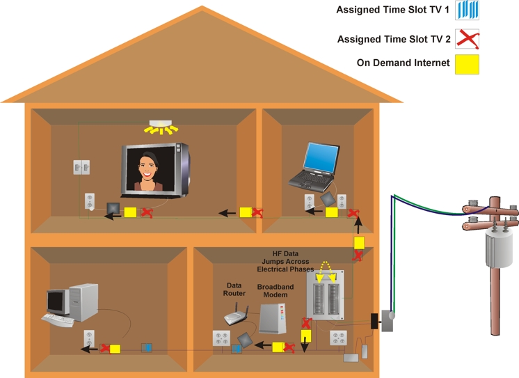
tion involves either reserving time periods for transmission and/or dynamically coordinating access by listening to the signals on the power line to ensure there is no existing activity before they transmit and stopping transmission when they detect data transmission collisions have occurred. Figure 3 shows how a HomePlug AV system can allow a power line distribution system to dynamically interconnect devices by connecting devices to electrical outlets and using high frequency signals to transfer information. This example shows that a HomePlug adapter coordinates the transmission of signals without interfering with the transmission between other devices. In this diagram, an IPTV service provider is sending a movie through a broadband modem to a television in the home. This example shows that the HomePlug system uses a HomePlug AV router to receive the signals from the broadband modem and route the information through the power lines to the television in the home using dedicated time slots to ensure a reliable quality of service (QoS). This example shows that simultaneously, a computer is connected through a HomePlug AV adapter to the in-home broadband modem allowing it to connect to the Internet and transfer data on an "as available" basis.
|
|
|
|
| Figure 1, Power Line Communication Control System | |
|
Who sets up IPTV Powerline PDNs? It is possible for customers to self-install a HomePlug AV system. The system is setup to automatically detect (discover) other devices in the network. While most HomePlug devices are pre-configured with the most common settings, it is possible to customize the configuration of the HomePlug adapter devices by connecting them to a local computer and allowing the user to change key settings such as IP addresses and passwords. What Media Types can be sent on HomePlug AV? All media types that can be converted to a digital form (audio, data and video) can travel over HomePlug AV. |
What Types of Equipment are needed for HomePlug Networks? Each device connected to a HomePlug system must have an Ethernet or USB port, which allows a connection to an adapter or have a HomePlug AV transceiver embedded within a platform. The adapter can be an external box or it can be designed into a product (such as a CD player). Adapters can be simple conversion devices (Ethernet to HomePlug) or they can include some packet transfer capability (routers or bridges). A HomePlug Ethernet bridge allows packets from a HomePlug network to enter into an Ethernet network (such as allowing data to the Internet). HomePlug devices include nodes and bridges. Nodes simply convert data signals into the frequency signals that travel on the power lines. HomePlug bridges allow data packets to cross over into devices or other networks without any need to use configuration utilities. What Transmission Speeds can be Achieved? The HomePlug AV powerline technology theoretical PHY transmission rate is 200 Mbps. There is a difference between physical data
|
pg 70 March 2006
|
transmission rates (the "PHY" rate) and actual data throughput. The throughput is affected by the amount of overhead (control) data and the amount of information that is lost via interference and the access control process. Even with the overhead control information, the HomePlug AV system can have data transmission rates in excess of 100 Mbps. Are there Key Compatibility Considerations for HomePlug Products? HomePlug AV technology is designed to co-exist with a variety of other systems including HomePlug 1.0, HomePlug 1.0 with Turbo, X-10, CeBus and LONworks. |
The typical range of a HomePlug signal is approximately 1000 feet (300 meters). HomePlug technology generally works in most homes. A broad-based product ecosystem is rapidly forming for HomePlug AV technology. This ecosystem includes set-top boxes, routers, gateways, switches, displays, TVs, DMAs and entertainment electronics platforms. HomePlug devices that are certified to operate under the HomePlug specification will interoperate with each other. |