|
 |
|
The 802.11n Wi-Fi standard has been enhanced to allow the sending of multiple video signals over extended distances. We had the opportunity to learn from Gill Epshtein, director of product marketing for Metalink on how the company uses the new 802.11n capabilities to allow up to three HD digital television channels to be sent over 802.11n Wi-Fi system. Legacy (older) IEEE 802.11a/g WLANs standard were not designed to provide the data rates and variable QoS levels needed to mix voice, data and video services over a single WLAN system.
Metalink has developed a solution that uses new capabilities for 802.11n include allowing multiple types of devices to share a WLAN system with different QoS requirements. 802.11n channels can be bonded (combined) so that their data transmission rates are higher than |
a single Wi-Fi radio channel can provide. Through the use of more efficient data coding and combining multiple transmission paths (MIMO), the operational distances (range) for a WLAN system can be extended. The 802.11n system can also use a more efficient channel access methods MAC which increases the overall transmission throughput (lower overhead). Metalink's solution utilizes the less congested 5GHz frequency band which helps to improve the overall transmission rate through reduced interference levels.
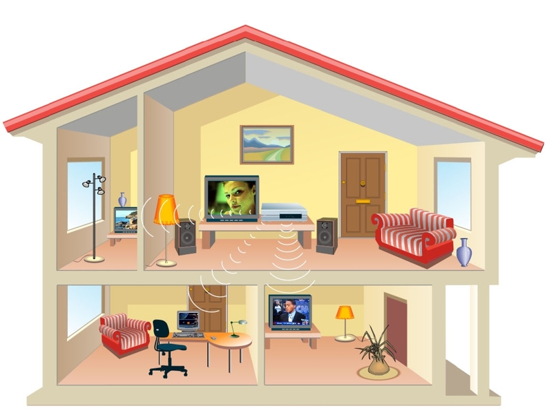
Figure 1 shows how an IP STB with Wi-Fi can communicate with several television viewing devices and other types of computing devices within a home. This example shows a home that has multiple televisions and a computer. The IP STB can coordinate and assign different QoS levels to the video and data communication devices within |
|
|
|
 |
|
Figure 1: The Wi-Fi Digital Home - A Mix of Video and Data Devices |
|
the home when serves and an access point or to communicate with a multimedia AP that resides in the house.
Quality of Service (QoS) for Video
Quality of service (QoS) is one or more desired performance and priorities of a communications system. QoS measures may include service availability, maximum bit error rate (BER), minimum committed bit rate (CBR) and other measurements that are used to ensure quality communications service.
The QoS performance requirements for video are different than data applications. Video transmission typically requires guaranteed bandwidth to satisfy customer expectations for "wire-like" performance. Assuring high bandwidth is a must, but this alone is not sufficient. When several applications try to access the same bandwidth, the ones that are intolerant to time delays and bandwidth fluctuations will not function properly.
Legacy 802.11 Wi-Fi protocols primarily use the distributed coordination function (DCF) access method to the wireless medium. This protocol defines a mechanism in which a station that would like to use the wireless medium must first listen and see if it is idle. If it is not idle, then the station starts a back-off timer with a random back-off interval, based on a predetermined range defined by the network parameters. The DCF provides an equal chance for each device to access the wireless medium, and works well in traditional data applications. In these applications, users don't notice that they share the wireless medium with others, because these applications are not sensitive to latency and jitter. In contrast, video, gaming and other applications are intolerant to bandwidth fluctuations, and so the fairness-access mechanism provided by DCF is inadequate.
Unique Wireless Medium Characteristics
WLANs are exposed to external impairments including other types of equipment operating in the same frequency range (e.g., Bluetooth devices, cordless phones and microwave ovens). These networks must cope with rapidly changing interference conditions. Reduction in available bandwidth due to limited radio coverage and interference from other devices causes an increased number of retransmissions which directly affect latency and jitter. The end result is lower available throughput, higher delays, and increased jitter as compared to wired LANs. As a result, video transmission over WLANs must cope with far more bandwidth variations, transmission delays and network congestion than are typically experienced in wired networks.
In general, there are two main approaches for addressing these issues; make the video devices less sensitive to special WLAN characteristics |
or to make the WLAN itself cope more effectively with the dynamics of video applications. The 802.11 standards committee created a new standard, 802.11n, that uses an enhanced version of legacy 802.11 Wi-Fi standards to enable transmission of digital video over Wi-Fi without the need to modify the digital video equipment.
The system uses a new physical-layer (PHY) that is capable of providing raw data rates on the order of 200 Mbps. Is uses a more efficient media access control (MAC) layer and it can provide several QoS levels for different types of devices. The combination of these new capabilities allows for the sending of up to three HD video signals over an 802.11n Wi-Fi system.
Video over WLANPlus™
In order to provide a wire-like experience using a WLAN, Metalink has developed WLANPlus technology which is designed to support the emerging IEEE 802.11n standard is focused on these main issues:
Increased Throughput
Enhanced QoS
Extended Reach
The WLANPlus system uses these key attributes to provide video over Wi-Fi:
Multiple Input Multiple Output (MIMO) Technology
Channel Bonding
Use of the 5 GHz band
Advanced Forward Error Correction (FEC)
Improved MAC efficiency
Jitter cancellation and Clock Recovery
Support of IEEE 802.11e QoS standard
Higher Throughput
Video distribution throughout a house requires much higher bandwidth than data applications. IPTV systems can use different types of video formats and compression techniques and the choice affects the video stream rate and its quality. A typical standard-definition television (SDTV) stream consumes 2 to 4 Mbps. A DVD-quality stream consumes 8 to 10 Mbps, while a high-definition television (HDTV) stream consumes approximately 18 to 24 Mbps using the MPEG2 compression scheme. Video distribution will invariably involve multiple streams, which requires effective throughput of ~ 60 Mbps to enable delivery of three HDTV streams.
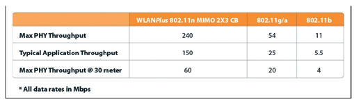
Figure 2 shows the data transmission rate throughputs for 802.11 WLAN systems. This table shows that the maximum data transmission for a bonded channel system (such as the Metalink WLANPlus) is 240 Mbps as compared to 54 Mbps for 802.11g/a or 11 Mbps for 802.11b. |
|
 |
|
Figure 2: Over-the-Air Transmission Rates and Effective Throughput |
|
This table also shows that the typical usable data transmission rate can be 40% to 50% less than the maximum data transmission rate at close distances and the usable data transmission rate decreases as the distance from the transmitter increases.
MIMO technology Provides Breakthrough Performance
MIMO technology is a signal processing and smart antenna technique for transmitting multiple data streams through multiple antennas and achieving higher rate, extended range, and better spectral efficiency than possible with legacy wireless systems. A conventional radio uses a single antenna to transmit a data stream, and a single antenna to receive it. A MIMO-based system uses multiple antennas to transmit simultaneously independent streams out of each antenna, all using the same frequency range. At the receive side, statistical multiplexing techniques utilize multiple instances of the data streams to recover the transmitted information.
MIMO is a multi-dimensional technology. It sends an independent data stream through each antenna, increasing the wireless spectrum utilization by a factor equivalent to the number of transmit streams (also known as the MIMO Rank).To accomplish this, MIMO utilizes spatial multiplexing (multiple antennas) on top of orthogonal frequency division multiplexing (OFDM). Coding the information across both the spatial and spectral domains by using multiple transmit and receive antennas, combined with OFDM modulation on each antenna, increases the diversity and, hence, the robustness. This enables MIMO to withstand channel impairments such as inter-symbol interference (ISI) and other interferences.
Another consideration is multi-path signals, which are the reflected signals arriving at the receiver some time after the original or line-of-sight signal is received. Multi-path is typically perceived as impairment in wireless systems, because it degrades the receiver's |
ability to recover the transmitted information. But in the case of MIMO, the network actually relies on multi-path for its operation.
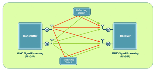
Figure 3 shows how multiple input, multiple output (MIMO) capabilities can use multiple transmission paths to assist in the transmission performance of the 802.11 system. This example shows that a transmitter and a receiver with two antennas can provide multiple transmission paths for the same signal. By combining the transmitted signals from multiple paths, the overall performance of the 802.11n system can be improved.
On the transmission side, MIMO encodes a single high-rate data stream by splitting it and transmitting it across spatially separated antennas. Each antenna carries a separate, lower-rate stream. However, multiple streams from multiple antennas are sent out using the same frequency spectrum. Having two streams instead of one enables either the delivery of twice the throughput by keeping the same rate for each of the streams, or extending the reach of the original stream since each of the lower-rate streams can use lower constellations and require a lower SNR to be recovered. On the receive side, the MIMO receiver uses mathematical algorithms to recover the transmitted signals and combine them into a single stream. The main advantages of MIMO include higher data transmission rate by a factor equal to the number of transmit streams, and the ability to establish a wireless connection in multi-path environments. Better SNR in reference to a legacy single input single output (SISO) system enables extended reach. Multiple receive antennas can enhance the operation in comparison to legacy systems by using maximum ratio combining (MRC) between receive antennas.
Channel Bonding
Channel bonding is the process of combining two RF channels to form a new communication channel that can use and manage the combined capacity of the bonded transmission channels. The 802.11n
|
|
 |
|
Figure 3, Using Multi-Path Transmission to Enhance 802.11 Performance |
|
system has been enhanced to allow two radio channels to be combined to increase the overall data transmission rate. Typically, doubling the available radio channel frequency bandwidth doubles the achievable rate.
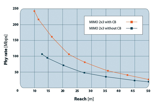
Figure 4 shows the data transmission rate performance of an 802.11 system with channel bonding and without channel bonding. This example uses MIMO which improves data transmission rates on both bonded and unbonded channels. This diagram shows that data transmission rate for two bonded channels is approximately double the data transmission rate of a single channel. |
5 GHz Band Used for Improved Performance
Two spectrum bands are available for WLAN communication: the 2.4 GHz band (2.4 GHz to 2.4835 GHz) used today by the IEEE 802.11b and IEEE 802.11g standards, and the 5 GHz band (5.15 GHz to 5.85 GHz), currently used by the IEEE 802.11a standard. The 2.4 GHz band can accommodate up to three non-overlapping 20MHz channels, which imposes hard limitations on the number of users that can be served and the number of adjacent networks that can operate without
|
|
 |
|
Figure 4: Data Transmission Rates for Single Channel and Bonded Channel Transmission |
|
interference. As explained before, channel bonding is an essential tool to meet the performance rate and reach targets for video delivery. A 60 Mbps effective throughput is more than double the maximum effective throughput that can be achieved without channel bonding with IEEE 802.11a/g standards. However, since only three channels are available in the 2.4 GHz band, channel bonding is not a feasible option. Adding to the challenge is the interference resulting from home microwaves, Bluetooth devices and cordless phones, which all operate at the same band. Given these channel-bonding and interference issues, the 2.4 GHz becomes irrelevant for quality home video distribution. The 5 GHz band offers more than twenty 20MHz channels in most parts of the world, which allows the support of much higher numbers of users, much higher bandwidth per user, and higher immunity from interference.
Advanced Forward Error Correction Scheme
Forward error correction is a mathematical algorithm that is used to produce extra bits of data that are sent each packet. The sending of FEC bits allows for the correction of information bits that were lost or changed due to noise or other physical effects. While FEC increases the reliability and robustness of the system, the extra bits increase the data rate required for a given transmission and reduces the amount of user data that is actually transmitted.
Metalink 's WLANPlus solution uses an optional low density parity check (LDPC) coding system instead of the legacy convolution code used by other IEEE 802.11 standards. An LDPC code is a linear block code specified by a very sparse parity-check matrix. LDPC provides coding gain which is higher by ~ 3 dB than the convolution code, and was already verified and adopted by DVB-S2 satellite broadcast and 10 Gigabit Ethernet over Copper system specifications. The additional coding gain (the increased efficiency of error correction process) can be used to extend the reach for the same data rate (3 dB of LDPC coding gain translates into up to 30 percent improvement in range, to increase the throughput (by using higher constellation) or to increase the robustness and immunity to interference. The coding benefit of LDPC is highest when low packet error rate (PER) and high data rates are required. This is an advantage in high bandwidth demand applications such as video distribution.
Improved MAC Efficiency
Medium access control is the processes used by communication devices to gain access to a shared communications medium or channel. The amount of bandwidth or percentage of time that is dedicated to medium access control is MAC overhead and the ratio of how much |
user data can be transmitted as compared to the total amount of available bandwidth or channel capacity is called the MAC efficiency. MAC efficiency of IEEE 802.11a/b/g is typically about 50 percent at the best conditions.
The WLANPlus system increases the MAC efficiency to 70 percent by using an aggregation scheme for packets assigned to the same destination, thus eliminating the overhead linked to each packet and replacing it with a 10 common overhead. Aggregate exchange sequences are made possible with a protocol that acknowledges aggregated MPDUs (A-MPDU) with a single block acknowledgement (Block ACK) instead of multiple ACK signals. The ability to identify the receive status of each packet within the block enables retransmission of only the specific packets that were not received properly. This protocol effectively eliminates the need to initiate a new transfer for every
MPDU.
The common overhead associated with each Multiple MAC protocol data unit (MPDU) transmission of IEEE 802.11a/b/g, is now associated with a large number of MPDUs. This proportionally increases the efficient throughput. Up to 32 MPDUs with the same destination address and priority are aggregated into a single concatenated payload, called an aggregated MPDU
(A-MPDU).
Enhanced Quality of Service (QoS)
The WLANPlus system uses new access control protocols and jitter cancellation and clock recovery processes to increase the quality of service
(QoS).
IEEE 802.11e Access Control Protocol
Access control is the actions taken to allow or deny use of the services and features of a communication system to individual users. The existing 802.11 access protocols primarily use the distributed coordination function (DCF) access method to the wireless medium. The DCF provides an equal chance to each device to access the wireless medium. When dealing with video, gaming and other applications that are intolerant to bandwidth fluctuations, the fairness access provided by DCF is inadequate.
The IEEE 802.11e standard adds new access control protocols to assign different priorities for different types of services. The first is enhanced distributed channel access (EDCA), which defines four priority levels or four access categories (ACs) for different types of packets. The second is hybrid coordination function controlled channel access (HCCA), which guarantees reserved bandwidth for packets classified based on EDCA by using a central arbiter for the bandwidth usage. |
|
|
|
When operating in DCF mode, all stations try to access the wireless medium with the same priority. When operating in EDCA mode, there are four levels of priority or ACs. The mechanism of listening to the medium and using a back-off mechanism to determine the allowed transmission time is similar to that defined by DCF. However, unlike DCF, the maximum back-off times are different for the different ACs, meaning that higher-priority ACs have a shorter maximum back-off time than lower-priority ACs. The shorter maximum back-off time allows the higher-priority AC to win access to the wireless medium more frequently than the lower-priority AC. Once a device has gained access to the wireless medium, it has the opportunity to continue transmitting for a specified transmission opportunity (TXOP). Applications or packets that share the same AC also have the same maximum back-off time and, hence, the same chance to gain access to the wireless medium. EDCA is fairly simple to implement, but cannot guarantee latency, jitter or bandwidth.
HCCA uses another approach to guarantee QoS. Instead of waiting for an idle time for transmission and using a back-off mechanism, HCCA relies on centralized control by the access point that can guarantee time and duration of transmission for each of the connected stations. Every station that would like to join the network must request permission from the central access point. This request includes a traffic specification that details the QoS required by the station. The access point then determines if it can support the requested QoS specifications and admits or denies station. The access point maintains a centralized schedule that is based on the QoS requirements of all of its registered stations. Then, the access point notifies each of the stations about the time it will have access to the wireless medium. Since this process is managed from a central location, it is guaranteed that the access will be contention-free. Because everything is predetermined upon registration, HCCA is able to guarantee bandwidth, jitter and latency, which is otherwise a difficult challenge in a mixed data and multimedia environment. |
Jitter Cancellation and Clock Recovery
Jitter is a small, rapid variation in arrival time of a packets and video transmission is very sensitive to these variations. Live real-time video streams are synchronous in nature. Video packets (e.g. MPEG2) carry time information via internal-time-stamps, such as program clock reference
(PCR) and presentation time stamp (PTS). These packets originated at the video source are required at the destination in order to ensure necessary video presentation quality. Timestamp usage requires that clocks at both ends be synchronized. TV networks (e.g. digital video broadcasting, or
DVB; and advanced television systems committee, or ATSC) ensure this synchronization while guaranteeing limited delay variation (jitter) between received packets. The actual jitter
specifications are linked to the specific implementation but, in general, MPEG video streams have strict requirements regarding allowable jitter tolerance. Meeting these specifications is crucial for proper operation. If jitter occurs outside of certain parameters, quality will be degraded to an unacceptable level.
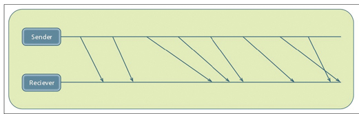
When video streams are transported over asynchronous communication networks like packet-based and wireless networks, jitter is inevitably introduced. This eliminates the synchronous nature of the video-traffic. There are many causes for jitter in wireless systems, including the lack of guaranteed bandwidth. Other causes include packet aggregations, packet length, transmission opportunity, packet retransmission, prioritization of multiple streams, etc. Figure 5 shows the variation that may occur in the transmission of packets from the sender to the receiver in a Wi-Fi network.In order to restore the synchronous nature of the video-streams and enable the use of time stamps, the receiver must compensate for the jitter introduced by the network, and a clock synchronization mechanism between sender and receiver must be established. |
|
 |
|
Figure 5: Variation in Packet Transmission over Wi-Fi |
|
Jitter can be handled using a jitter buffer. The video frames at the receive side are first stored in a buffer and then may be played out in a constant rate, in the case of constant bit rate (CBR) video. Alternatively, the video frames may be played out according to time-stamp information, such as in the case of variable bit rate (VBR) video. The size of the jitter buffer determines the delay introduced, so eventually there is a tradeoff between buffer size and latency. If the jitter tolerance is beyond the range of the buffer size, video frames will be discarded and the quality of the picture will be hurt. In addition, the jitter-buffer mechanism needs to ensure no buffer over-run or under-run to eliminate packet loss. Although jitter can be handled using a jitter buffer, it is still important to consider the jitter buffers size, not only because of cost, but because a jitter buffer introduces constant latency to the stream. While stored playback applications can usually afford to use a larger jitter buffer and its associated large constant latency, interactive and live streams are very sensitive to the increased latency associated with this approach.
Most common decoders cannot lock on the encoder clock when jitter exceeds 500 nsec. Most digital video system use the MPEG transport standard and in order to be able to interpret the MPEG presentation and timing information in the right way, the decoder-clock needs to be locked on the encoder-clock. If the encoder is not locked onto the decoder clock, overflow and underflow might occur at the decoder buffer, which risks creating packet-loss. When passing through asynchronous packet-network like a wireless network, a much higher jitter might be introduced and a jitter cancellation mechanism is required.
There are several mechanisms to cancel jitter and all share the same basic requirement, to have a common clock at the sender & receiver. Since traffic is variable bit rate (VBR), a jitter-buffer at the receiver-edge of the asynchronous network can be used in conjunction with timestamps signature at the sender-edge of the asynchronous net |
work. These timestamp will inform the jitter-buffer mechanism exactly when to play-out the next packet. However, interpreting the timestamps at the receiver exactly at the form originated by the sender requires clock-synchronization between the sender timestamp mechanism, and the receiver jitterbuffer timestamp mechanism. Otherwise, the jitter buffer can overflow or underflow along the time, and packets will be lost. There are many algorithms, which allow clock recovery between network ends in the presence of jitter. Basically when there is no jitter (constant delay) a simple PLL mechanism with time-stamps will be sufficient.
Time stamps are sent each period of time from sender to receiver, and the difference between the timestamps reflects the difference between the clocks. This information is used by the PLL mechanism to lock the clocks. Since constant delay is not usually the case of asynchronous packet network, algorithms were developed to evaluate the network-jitter, and isolate it from the clock difference. Such isolation is required in order to be able to correct the sent timestamps so the difference between them reflects only the clock difference and not the network jitter. This capability requires sophisticated mechanism to measure the network jitter with very fast response time. Metalink's WLANPlus is specifically designed taking these issues into consideration, enabling to overcome the jitter cancellation and clock recovery challenges in delivery of video over wireless networks.
Extended Reach
Extended coverage requirements are distances that a system is required to provide that goes beyond the common distances that system can provide. While we got used to "dead spots" and limited coverage for home data networks, this is not acceptable with wireless video net |
|
 |
|
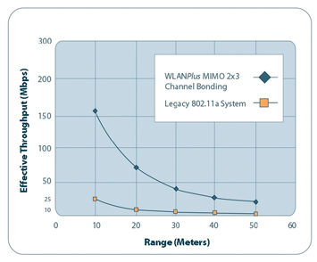
Figure 6: Increased Transmission Throughput over Greater Distances |
|
works. Users demand a centralized multimedia storage device that can act as the source of all multimedia content, and which can communicate with all possible players and other content storage devices throughout the house.
For Wi-Fi data applications, the bit rate can drop with increased distance from the access point and there is little if any impact on performance. However, for Wi-Fi video applications, it is critical that the bit rate remains sufficient throughout the coverage area, which, in this case, is a complete house. Legacy IEEE 802.11a/g networks are simply incapable of providing these performance assurances and the required bit rate for a single HDTV stream cannot be delivered outside a typical living room.
The combination of MIMO, reduced interference levels and improved coding efficiency allow for extending the reach of WLAN systems. Optionally, the extra bandwidth that is available from channel bonding can be used to increase the range of the system by allowing the use of a more robust modulation type (applying a lower constellation) allowing improved data reception in areas that have lower signal to noise ratios. |
Figure 6 shows how the WLANPlus system can provide increased throughput over greater distances. This diagram shows that
the WLANPlus system can provide data transmission rates of over 25 Mbps at 30 meters (100 feet) as compared to the 802.11a system that can provide 25 Mbps at only 8 meters (25 feet). |

Gil Epshtein is a senior product manager at Metalink. He is responsible for its WLANPlus product line.
Metalink Ltd. (NASDAQ: MTLK) is a leading provider of high performance wireless and wireline broadband communication silicon solutions. The company enables true broadband connectivity in every home through cost-effective, very high-speed delivery of advanced applications. |
|
|
|